TP4056 module is a constant current-voltage linear charging circuit board designed for single 3.7V lithium cells. It continuously monitors the voltage level of the Li-Ion/Li-Pol cell during both the charging and discharging phases to provide overcharge and short-circuit protection. Operating with a 5V 1A DC voltage, it can be powered through a USB A to Micro-B cable, typically from a smartphone adapter. The module's low external component count makes it particularly well-suited for portable electronics applications. You can buy this module here!
Specifications of TP4056 Lithium Cell Charger Module
The quick technical specifications of this charging module is given below:
- Type: 18650 Charger & Current Protection Board
- Module IC: TP4056 SOP-8 Chip
- Cell Type: Li-Ion, Li-Pol
- Cell Voltage: 3.7 V
- Power Connector: Micro-B USB
- Input Voltage: 4V to 8V
- Input Current (Max.): 1050 mA (~1A)
- Charging Voltage: 4.2 V
- Charging Current: 1 Amp (default)
- Charging Precision: 1.5%
Pin Configuration of TP4056 Lithium Cell Charger Module

The device pinout displays all the connection pins. The following table depict all the pin types along with the function of each pin.
| Pins | Description |
|---|---|
| IN+ | Alternative +5V input supply to the device |
| IN- | Device ground |
| B+ | Supply positive output supply for charging a 3.7V lithium cell |
| B- | Supply negative output for charging a 3.7V lithium cell |
| OUT+ | Supply positive output from the connected lithium cell to the load |
| OUT- | Ground to the load and sensing the short-circuit |
TP4056 Lithium Cell Charger Module Circuit Diagram
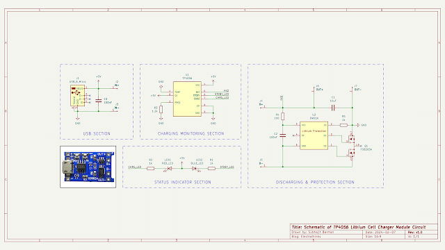
Schematic of the TP4056 chip based 3.7V lithium cell charging/discharging module circuit with short circuit protection is shown below.

The hardware components are used in the circuit are - TP4056 SOP-8 IC (U1), DW01A SOT23-6 IC (U2), FS8205A TSSOP-8 IC (Q1), Micro USB type-B (J1), 10uF ceramic capacitor (C1), 100nF ceramic capacitor (C2, C3), Red LED (LED1), Blue LED (LED2), 1k resistor (R1, R2, R5), 1.2k resistor (R3), and 100 Ohm resistor (R4).
Working Principle of TP4056 Lithium Cell Charger Module Circuit
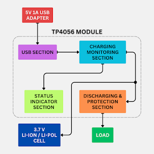
Lithium-Ion or Lithium-Polymer cells may explode if shorted, overcharged, or charged/discharged with too high currents. The TP4056 module is a combination charger and protection system for a single 3.7V lithium cell. Inside the charger module circuit, the TP4056A, DW01A, and FS8205A (Dual N-Channel MOSFET) chips are used. The circuit comprises four sections, each with different functionalities.

- USB Section. A standard female micro USB Type-B port is integrated into the circuit board to receive power (VCC +5V, 1A). This requires a male micro USB Type-B to male USB Type-A cable to connect the module to the smartphone adapter.
- Charging Monitoring Section. This section monitors the voltage level of the lithium cell during charging and discharging with the help of TP4056A linear voltage IC, and it stops charging at 4.2V. The charge current is initially set to a default of 1A by the programmable resistor (R3), and the output charging current can be further adjusted by replacing the recommended resistor value from the table below.
Resistor (R3) Charging Current 10k 130mA 5k 250mA 4k 300mA 3k 400mA 2k 580mA 1.66k 690mA 1.5k 780mA 1.33k 900mA 1.2k 1000mA - Status Indicator Section. During the charging process, the CHRG pin of the TP4056A chip goes high, turning on the red LED to indicate that the 3.7V cell is charging. Once the charger fully charges the lithium cell to 4.2V, it automatically lowers the CHRG pin voltage and raises the STANDBY pin voltage of the chip, turning on the blue LED to indicate completion.
- Discharging & Protection Section. The connected lithium cell can be safely discharged by a load and protected with current sensing circuitry. The DW01A lithium cell protection IC safeguards the 3.7V lithium cell from damage or degradation caused by overcharge, over-discharge, and short circuits. No blocking diode is required due to the internal N-MOSFET architecture of FS8205A, preventing negative charge current circuits.
If the output is shorted, the current sensing pin (CS) of the DW01A chip detects the issue and immediately disconnects the closed path between the lithium cell and the load circuit by controlling the gate voltage of the FS8205A intregrated MOSFETs.
This is how the TP4056 lithium cell charging/discharging module circuit works.
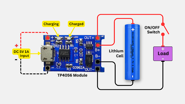
Connection Diagram of TP4056 Lithium Cell Charger Module

|
| It illustrates the connection between the TP4056 module and a 3.7V lithium cell for charging, as well as the connection with a load for discharging the stored charge. |


No comments
If you have any doubts or questions, please let me know. Don't add links as it goes to spam. Share your valuable feedback. Thanks