In this project, I have shared a pocket-sized inductance meter using Arduino, capable of precisely measuring 41uH to 30mH inductance values. Additionally, it can easily measure lower and higher inductance values than the specified range. The measured values are displayed on the OLED screen. It is a cost-effective comparative alternative to industrial LC meters, making it suitable for electronics hobbyists or beginners. Let's make it!
Arduino Inductance Meter Circuit Diagram
The schematic of the inductance meter circuit using Arduino is shown below.

The following components are used in this DIY inductance meter circuit:
| Hardware components | Designators | Quantity |
|---|---|---|
| Arduino Nano/Uno | U1 | 1x |
| LM339 Single Supply Quad Comparators | U2 | 1x |
| I2C/IIC 4-Pin OLED Display Module (128x64) | U3 | 1x |
| 150 Ohm Resistor | R1 | 1x |
| 1k Ohm Resistor | R2, R3 | 1x |
| 1N4001 Diode | D1 | 1x |
| 2.2uF Tantalum/Electrolytic Capacitor | C1 | 1x |
| ? | L1 | 1x |
Working Principle of Arduino Inductance Meter Circuit
The meter operates on the principle of the LC oscillator, generating a resonant frequency that is inversely proportional to the inductance being measured. By measuring this frequency, we can determine the inductance value.

The LC oscillator is the heart of the Arduino Inductance Meter circuit, consisting of an inductor (L) with an unknown inductance and a capacitor (C) with known capacitance connected in parallel circuit.

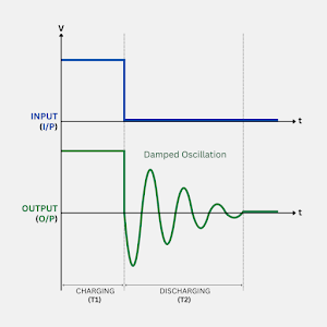
When the Arduino applies a 5 volts pulse to the LC circuit, the capacitor starts charging (T1) through the inductor. As the capacitor charges, the energy stored in the magnetic field of the inductor increases. After that, the pulse is stopped, and the capacitor starts discharging (T2) through the inductor. This discharge causes the energy stored in the magnetic field to decrease. This charging and discharging cycle continues, resulting in a damped oscillation.

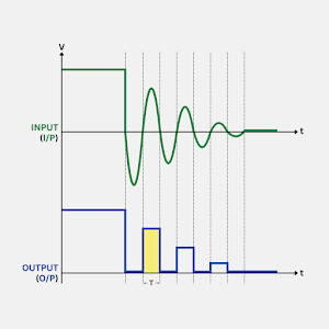
Now, a zero-crossing detector (ZCD) circuit using LM339 comparator, becomes high for the positive half of each Cycle of the sine wave. This results in a square wave with the same frequency as the damped oscillation that the Arduino will detect and measure (more than 3µS long) using the pulseIn function. It measures the time (T) period of the first square wave signal after the LC circuit is discharged. The frequency (F) of the oscillation is then calculated by the following formula: F = (1 / 2T).
To calculate the unknown inductance, Arduino uses the resonance frequency equation of the LC circuit: L = (1 / (4 * π2 * F2 * C)).
By measuring the frequency and knowing the value of the capacitor, the Arduino calculates the inductance value and prints it on the OLED screen. The output result may vary slightly with each reading due to the tolerance of the selected capacitor. It is important to measure the actual capacitance value of the capacitor and update it in the Arduino programming code.
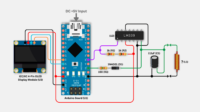
Connection Diagram of Arduino Inductance Meter

|
| It illustrates the connection between the Arduino board, 128x64 OLED display module, and LM339 with a few electronic components. |
Programming Code for Arduino Inductance Meter
Here is the Arduino programming code to measure the unknown inductance value of an inductor. Please note that before uploading the sketch, add the Adafruit GFX and Adafruit SSD1306 libraries in your Arduino IDE.
#include <Wire.h>
#include <Adafruit_GFX.h>
#include <Adafruit_SSD1306.h>

#include <Fonts/FreeSans9pt7b.h>
#include <Fonts/FreeSans12pt7b.h>
#include <Fonts/FreeSansOblique12pt7b.h>

#define SCREEN_WIDTH 128
#define SCREEN_HEIGHT 64

// Initialize the SSD1306 display object
Adafruit_SSD1306 display(SCREEN_WIDTH, SCREEN_HEIGHT, &Wire, -1);

// Declare variables for pulse, frequency, capacitance, and inductance
double pulse, frequency, capacitance, inductance;

void setup() {
  // Initialize the I2C communication
  Wire.begin();

  // Initialize the SSD1306 display with I2C address 0x3C
  display.begin(SSD1306_SWITCHCAPVCC, 0x3C);

  // Wait for 1 second, then clear and display the OLED screen
  delay(1000);
  display.clearDisplay();
  display.display();

  // Initialize serial communication with a baud rate of 115200
  Serial.begin(115200);

  // Set pin 5 as INPUT and pin 3 as OUTPUT
  pinMode(5, INPUT);
  pinMode(3, OUTPUT);

  // Wait for 200 milliseconds
  delay(200);
}

void loop() {
  // Generate a 5 microseconds HIGH pulse on pin 3
  digitalWrite(3, HIGH);
  delay(5);
  digitalWrite(3, LOW);
  delayMicroseconds(100);

  // Measure the duration of the HIGH pulse on pin 5
  pulse = pulseIn(5, HIGH, 5000);

  // Check if the measured pulse duration is greater than 0.1 microseconds
  if (pulse > 0.1) {
    // Update with your specific capacitance value
    capacitance = 2.08E-6;

    // Calculate frequency and inductance using the measured pulse duration
    frequency = 1.0E6 / (2 * pulse);
    inductance = 1.0 / (capacitance * frequency * frequency * 4.0 * 3.14159 * 3.14159);
    inductance *= 1E6;

    // Print measurements to the Serial Monitor
    Serial.print("High for uS:");
    Serial.print(pulse);
    Serial.print("\tfrequency Hz:");
    Serial.print(frequency);
    Serial.print("\tinductance uH:");
    Serial.println(inductance);
    delay(10);

    // Display measurements on the OLED screen
    display.clearDisplay();
    display.drawRect(0, 0, SCREEN_WIDTH - 1, SCREEN_HEIGHT - 1, SSD1306_WHITE);

    display.setFont(&FreeSans9pt7b);
    display.setTextColor(SSD1306_WHITE);
    display.setCursor(6, 25);
    display.print("Inductance:");

    // Choose appropriate units (uH or mH) based on the magnitude of inductance
    if (inductance > 999) {
      inductance /= 1000.0; // Convert to millihenries (mH)
      display.setFont(&FreeSans12pt7b);
      display.setCursor(6, 52);
      display.print(inductance);
      display.setCursor(58, 52);
      display.print("mH");
    } else if (inductance < 1000) {
      display.setFont(&FreeSans12pt7b);
      display.setCursor(6, 52);
      display.print(inductance);
      display.setCursor(85, 52);
      display.print("uH");
    }

    // Display on the OLED screen and wait for 2 seconds
    display.display();
    delay(2000);

  } else {
    // Inductor not connected, print "Unknown" in place of inductance
    display.clearDisplay();
    display.drawRect(0, 0, SCREEN_WIDTH - 1, SCREEN_HEIGHT - 1, SSD1306_WHITE);

    display.setTextColor(SSD1306_WHITE);
    display.setFont(&FreeSans9pt7b);
    display.setCursor(6, 25);
    display.print("Inductance:");

    display.setFont(&FreeSansOblique12pt7b);
    display.setCursor(6, 52);
    display.print("Unknown");
    display.display();
    delay(10);
  }
}
DIY Arduino Inductance Meter: Demo
I have just assembled and soldered the hardware components on a Veroboard as compactly as possible by following the schematic and uploading the code to the Arduino board.

|

|
| Circuit on Veroboard | Circuit on Custom PCB |
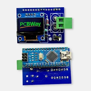
Honestly! Creating a manual track on Veroboard is difficult and time-consuming, with no guarantee of the best outcome. Opting for a professional online PCB service such as PCBWay.com ensures a high-quality result. You can order five inductance meter boards for only $5 by specifying the PCB requirements and submitting this Gerber file. The high-quality PCBs will be delivered to you in a few days or weeks, depending on the chosen service level.


No comments
If you have any doubts or questions, please let me know. Don't add links as it goes to spam. Share your valuable feedback. Thanks