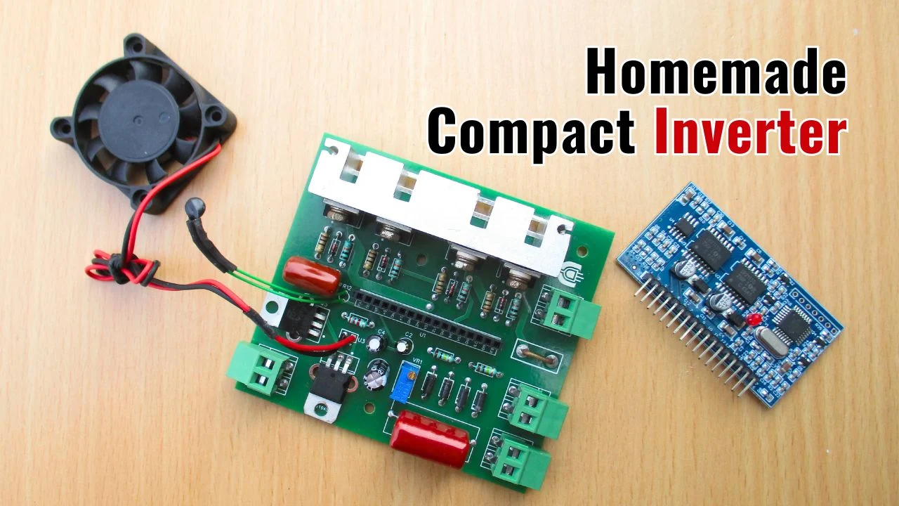
In this project, I will show you how to make a compact full sinusoidal inverter using EGS002 SPWM driver board, which can convert the input 12V DC to 220V AC output with 50/60Hz pure sine wave.

This inverter can power electric appliances up to 300 watts during emergency situations when electricity is not available in your house or can also be highly useful for camping and outdoor work where electricity is unavailable to operate low wattage tools like mobile/tablet charger, mini-drills, soldering equipment, and LED bulbs.
Let's make it!
Components list for this Homemade Inverter
The following components are required to make this Pure Sine Wave Inverter:
| Name | Value | Qty. |
|---|---|---|
| U1: Inverter Driver Module | EGS002 SPWM | 1 |
| Q1 to Q4: N-Channel MOSFET | IRF3205 | 4 |
| Q5: NPN Transistor | TIP31 | 1 |
| D1 to D4: Diode | 1N4148 | 4 |
| D5 to D8: Diode | 1N4007 | 4 |
| R1 to R4: Resistor | 10Ω, 1/4W | 4 |
| R5 to R8: Resistor | 10kΩ, 1/4W | 4 |
| R9: Shunt Resistor | 0.01Ω | 1 |
| R10, R11: Resistor | 100kΩ, 1/4W | 2 |
| R12: NTC Temprature Sensor | 10kΩ | 1 |
| R13: Resistor | 2.2kΩ, 1/4W | 1 |
| VR1: Variable Resistor | 10kΩ | 1 |
| C1: Capacitor | 2.2uF, 400V | 1 |
| C2: Capacitor | 2.2uF, 25V | 1 |
| C3: Capacitor | 100uF, 25V | 1 |
| C4: Capacitor | 10uF, 25V | 1 |
| C5: Capacitor | 470nF | 1 |
| T1: UPS Transformer | 7V /220V, 500W | 1 |
| U2: Voltage Regulator | IC 7805 | 1 |
| U3: DC Fan | 12V, 25mA | 1 |
| Heat Sink | Aliminium | 1 |
| Insulation Pads with Plastic Washers | Rubber/Plastic | 2 |
| Washers | Plastic | 2 |
| 17 Header Pin | Female | 1 |
EGS002 Pure Sine Wave 300W Inverter Circuit Diagram
Schematic of the 300w pure sine wave inverter circuit with egs002 spwm driver board is shown below.

I ordered the custom-designed PCB from www.PCBWay.com, and after a few days of waiting, I received the high-quality PCB.

Here, I'm sharing the egs002 pure sine wave inverter PCB Gerber file. You can download it and order it at a very affordable price from PCBWay. The circuit can handle 300W when the thickness of the copper on the outer layer is greater than 4 oz Cu.
PCB Connection Pinout Instractions
After soldering all components onto the shared EGS002 pure sine wave inverter PCB according to the schematic -

Follow the provided pinouts for connecting the transformer primary & secondary terminals to the PCB, as well as the power input DC and output AC connections.


No comments
If you have any doubts or questions, please let me know. Don't add links as it goes to spam. Share your valuable feedback. Thanks