A Blocking oscillator is a free-running square wave generator circuit usually configured with a resistor, a non-air gap transformer, and a transistor for amplifying. Its astable square wave output is commonly applied in SMPS circuits, voltage booster circuits, or similar switching circuits where sensitive electronic devices are not present.
Here, I will discuss, and explain the workings of this free-running pulse oscillator along with its circuit diagram. Let's get started!
Working principle of Blocking oscillator circuit
The working principle of a blocking oscillator circuit involves the amplifier device in the form of a BJT transistor being switched into a cut-off (i.e., blocked) state more frequently than it is allowed to conduct during the oscillation process.

|
| Schematic of a blocking osillator circuit with two winding transformer. |
This circuit can be used as a voltage booster for driving small loads such as LEDs. It works fine even if other circuits treat the battery as "dead." A minimum turn-on voltage of the transistor (0.7V for silicon, 0.4V for germanium) is sufficient to reach the required voltage level of the LED. This type of circuit is also called a Joule Thief, Joule Ringer, or Vampire Torch.
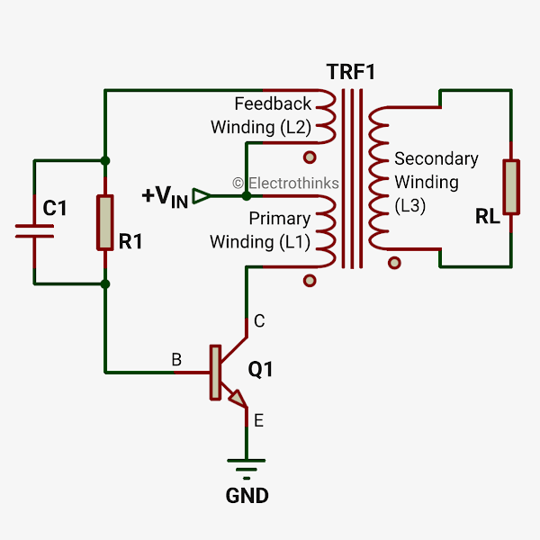
Initially, the input voltage flows through the transformer (TRF1) feedback winding (L2) and a parallel RC circuit to the base of the transistor (Q1), causing it to enter the "on" state. The input voltage now flows through the primary winding (L1), through the transistor's collector-base junction, and to ground. A magnetic field is induced in the non-air gap transformer core, reaching its maximum capacity but not able to store the magnetic flux.
When the transformer core is fully energized, the current can no longer flow through the collector base of the transistor, causing it to switch to the "off" state. At this point, the induced magnetic energy seeks to discharge rapidly as a voltage much higher than the input voltage due to the absence of a secondary winding.
In the presence of the secondary winding (L3), the primary winding induces mutual inductance, which results in the generation of a voltage (either step-up or step-down, depending on the winding turns) in the secondary.

|
| Schematic of a blocking osillator circuit with three winding transformer. |
Consequently, the capacitor (C1) discharges the stored voltage through the feedback winding more quickly than the parallel resistor (R1), creating an opposing magnetic field in the core. This magnetic energy impacts the voltage level in the primary and, as well, affects the secondary voltage.
The block oscillator circuit with a secondary winding in the transformer (TRF1) can be used as a high-voltage generator inside an insect trap or electric shock gadget. This type of inverter circuit requires a high current in the primary for pulse switching, and the number of turns is more in the secondary winding than in the primary or feedback winding. It isn't essential to use a capacitor (C1) in the circuit to maximize the secondary output.
Once the energy is dissipated by the load, the circuit effectively resets, and the entire process begins anew in a series of pulses, typically occurring at a rate of 50,000 times per second. The crucial disadvantage of this switching circuit is the power loss in the transformer core and its inability to maintain an output voltage as a pure square wave due to the addition of harmonic content.


No comments
If you have any doubts or questions, please let me know. Don't add links as it goes to spam. Share your valuable feedback. Thanks