

In this project, I will show you that how to monitor environmental humidity rage of 20% to 90% RH and room temperature range of 0°C to 50°C with a DHT11 sensor, where the Arduino measured digital data is displayed on a I2C OLED screen.
Let's make it!
Components for Humidity and Temperature Monitoring System
The following components are required to make this monitoring system:
| Name | Value | Qty. |
|---|---|---|
| DHT11 Sensor | KY-015 Module | 1 |
| I2C OLED | 128x64, 4-Pin | 1 |
| Arduino | UNO/Nano | 1 |
| Jumper Wire | Male to Male | 9 |
| DC Power Supply | 5V ~ 12V | 1 |
| Breadboard | Any | 1 |
Buy High-quality:
Interfacing DHT11 Sensor with Arduino and I2C OLED
Connection diagram of the DHT11 sensor with an Arduino and an I2C OLED for Humidity-Temprature monitoring system is shown below.
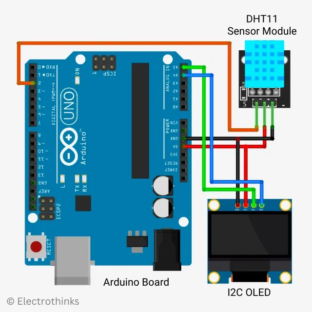
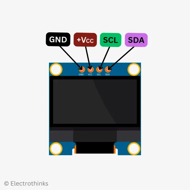
Before interfacing it, you need to understand the pinouts of the DHT11 Humidity & Temprature Sensor module and the I2C OLED 128x64.

|
|
The module has 3 male header pins those are —
|
The SSD1306 Driver based display has 4 male header pins those are —
|
After arranging all the required components, make the following pin connections on the breadboard using jumper wires.
| KY-015 Module | I2C OLED 128x64 | Arduino |
|---|---|---|
| S | — | Pin 2 |
| — | SCL | Pin A5 |
| — | SDA | Pin A4 |
| middle | VCC | Pin 5V |
| - | GND | Pin GND |
Here is the Arduino programming code to monitor environmental humidity and room temperature. Please note that before uploading the sketch, you will need to install certain libraries in your Arduino IDE. These include the DHT sensor library, Adafruit GFX library, Adafruit SSD1306 library, and the Adafruit unified library if required.
#include "DHT.h"
#define DHT11Pin 2
#define DHTType DHT11
//OLED
#include <Wire.h>
#include <Adafruit_GFX.h>
#include <Adafruit_SSD1306.h>
DHT HT(DHT11Pin,DHTType);
float humi;
float tempC;
float tempF;
//OLED define
#define SCREEN_WIDTH 128 // OLED display width, in pixels
#define SCREEN_HEIGHT 64 // OLED display height, in pixels
// Declaration for an SSD1306 display connected to I2C (SDA, SCL pins)
Adafruit_SSD1306 display(SCREEN_WIDTH, SCREEN_HEIGHT, &Wire, -1);
void setup() {
Serial.begin(9600);
//For DHT11
HT.begin();
//For OLED I2C
if(!display.begin(SSD1306_SWITCHCAPVCC, 0x3C)) { // Address 0x3D for 128x64
Serial.println(F("SSD1306 allocation failed"));
for(;;);
}
display.display(); //Display logo
delay(1000);
display.clearDisplay();
}
void loop() {
delay(1000);
humi = HT.readHumidity();
tempC = HT.readTemperature();
tempF = HT.readTemperature(true);
Serial.print("Humidity:");
Serial.print(humi,0);
Serial.print("%");
Serial.print(" Temperature:");
Serial.print(tempC,1);
Serial.print("C ~ ");
Serial.print(tempF,1);
Serial.println("F");
display.clearDisplay();
oledDisplayHeader();
oledDisplay(3,5,28,humi,"%");
oledDisplay(2,70,16,tempC,"C");
oledDisplay(2,70,44,tempF,"F");
display.display();
}
void oledDisplayHeader(){
display.setTextSize(1);
display.setTextColor(WHITE);
display.setCursor(0, 0);
display.print("Humidity");
display.setCursor(60, 0);
display.print("Temperature");
}
void oledDisplay(int size, int x,int y, float value, String unit){
int charLen=12;
int xo=x+charLen*3.2;
int xunit=x+charLen*3.6;
int xval = x;
display.setTextSize(size);
display.setTextColor(WHITE);
if (unit=="%"){
display.setCursor(x, y);
display.print(value,0);
display.print(unit);
} else {
if (value>99){
xval=x;
} else {
xval=x+charLen;
}
display.setCursor(xval, y);
display.print(value,0);
display.drawCircle(xo, y+2, 2, WHITE); // print degree symbols ( )
display.setCursor(xunit, y);
display.print(unit);
}
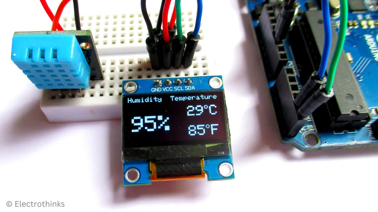
}Testing & Demo: Humidity and Temperature Monitoring System
I powered the Arduino board using a 5V USB power supply, and within a few seconds, the system detected humidity and temperature, displaying the measured values on the I2C OLED.
Why is not the I2C OLED displaying anything? — If your display does not turn on, disconnect the input power supply and short-circuit the OLED's VCC and GND pins for a few seconds. Then, reconnect the power supply, and notice that the display is now turned on.


 Circuit Working Explanation")

0 Comments: