Many electronic components, including microcontrollers, integrated circuits, sensors, displays, communication modules, and low-power devices, operate at lower voltages.
Voltage dividers are commonly used in electronics to scale voltages, generate reference voltages, interface with sensors, shift voltage levels, or attenuate signals. It provides a simple and effective way to control voltage levels in various electronic applications by adjusting the resistor values.
But the question arises do you know how does the resistor voltage divider works, what is voltage divider rule, and resistor voltage divider circuit diagram? Let's learn about Resistor voltage divider and Circuit diagram with working explanation.
What is Resistor voltage divider?
Resistor Voltage Divider is also called a potential divider or voltage division. It consists of two resistors connected in series, with the output voltage taken from the connection point between them. Electronic circuits use this technology to provide a desired voltage level by proportionally dividing the input voltage. Simply put, it is an electronic circuit that divides a voltage into smaller fractions.
Usually, the potentiometer is a three-terminal device that can be used as a variable voltage divider in electronic circuits. It consists of a resistive element with sliding contact, or wiper, that moves along the track.
Resistor voltage divider Circuit diagram
Schematic of a resisor voltage divider circuit is shown below.
Working principle of Resistor voltage divider circuit
The working principle of a resistor voltage divider circuit is simple. The total input supply voltage (VIN) is divided into the voltage across two resistors, namely (VR1) and (VR2), and the output is the voltage across resistor (R2). Furthermore, the current (I) through both resistors is the same.
We can apply Kirchhoff's Voltage Law and Ohm's Law to calculate the voltage drop across each resistor in terms of the same current flowing through them.
Using KVL (Kirchhoff's Voltage Law),
VIN = VR1 + VR2 ...(i)
With Ohm's Law,
VR1 = I x R1 ...(ii)
VR2 = I x R2 ...(iii)
Applying the two equations (ii) and (iii) to equation (i), you will get:
VIN = (I x R1) + (I x R2)
Or, VIN = I (R1 + R2)
Hence, I = VIN / (R1 + R2) ...(iv)
Now, compare the equations (ii) and (iv) to get the voltage across the resistor (R1),
VR1 = I x R1 = R1 x VIN / (R1 + R2)
Hence, VR1 = R1 x VIN / (R1 + R2) ...(v)
Similarly, compare the equations (iii) and (iv) to get the output voltage across the resistor (R2),
VR2 = I x R2 = R2 x VIN / (R1 + R2)
Hence, VR2 = R2 x VIN / (R1 + R2) ...(vi)
The above equations (v) and (vi) allow us to calculate and understand how voltage is distributed across the resistors in a voltage divider resistor series circuit.
Therefore, the voltage divider rule states that the voltage across any individual series component is equal to the product of its resistance value and the total supply voltage divided by the total resistance of the series circuit.
Resistor voltage divider circuit - Testing & Demo
Before performing the test, we need to calculate first. I choose test values where resistor (R1) is 330Ω and resistor (R2) is 470Ω, with a supply voltage (VIN) of 9V DC.
Calculations
Using equation (iv), I calculate the current (I) flow through the resistor voltage divider circuit. We get:
I = 9 / (330 + 470) = 11.25 mA
Next, using equation (v), I calculate the voltage accross the resistor 330Ω. We get:
VR1 = 330 x 9 / (330 + 470) = 3.71 V
For the output voltage, I calculate the voltage across the resistor 470Ω using equation (vi). We get:
VR2 = 470 x 9 / (330 + 470R) = 5.28 V
Let's compare below test results with the above-calculated values and verify whether the values match!
Circuit testing
First, I have assembled two resistors on the breadboard according to the resistor voltage divider schematic. Then, I give constant +9V DC to the circuit as a power source.
To measure the current flow through the voltage divider resistor series circuit, I connect a digital multimeter in series between the positive terminal of the input supply and the resistor (R1). The measured value is 11.15 mA.
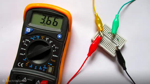
Next, I rearranged the circuit to default connections and measured the voltage across the resistor (R1) with the multimeter set to DC voltage (V). The measured value is 3.66 V.
Similarly, I am measuring the output voltage across the resistor (R2), which is 5.20 V.
You can notice the measured values of current flow and voltage across the resistors are almost identical to my calculated values.
The results are slightly different due to the internal impedance of the connecting wires and components. But this difference does not cause any problems in your circuit.


No comments
If you have any doubts or questions, please let me know. Don't add links as it goes to spam. Share your valuable feedback. Thanks