This is an excellent choice for a final year project in electrical engineering. In this project, I will present a design of an Automatic Power Factor Controller using Arduino, including an explanation of what APFC is, a circuit diagram, calculation, functional block diagram with a working explanation, source code, and more. Let's get started!
What is an APFC or Automatic Power Factor Controller?
It is a device that regulates and manages the power factor in an electrical system, also known as APFC. A good power factor is close to unity (1), indicating that the electrical system is efficiently utilizing power without excessive consumption of reactive power.
APFC monitors the power factor and adjusts the reactive power using capacitors to maintain a desired power factor. They are commonly used in industrial and commercial settings to ensure efficient power usage and avoid penalties from utilities for poor power factor.
As we know that Inductive loads are commonly connected to a power circuit, it can result in a decrease in the power factor. The Automatic Power Factor Controller (APFC) detects this and works to improve the power factor.
It is important to have a power factor close to unity because a low power factor leads to increased consumption of reactive power. This increased reactive power consumption can result in high current flow through the circuit, leading to heat generation, power losses, and other issues. Similarly, a high power factor can lead to voltage instability, voltage surges, and increased stress on the power system components. Therefore, both a highly lagging or leading power factor can be harmful to the electrical circuit.
To counterbalance this, a capacitive load is required to maintain the power factor. The APFC is equipped with capacitor banks that are utilized to enhance the power factor. These capacitors provide reactive power compensation, which helps to improve the power factor and ensure efficient operation of the electrical system. This improves energy efficiency, reduces losses, and optimizes electrical equipment performance.
Arduino APFC Circuit Diagram
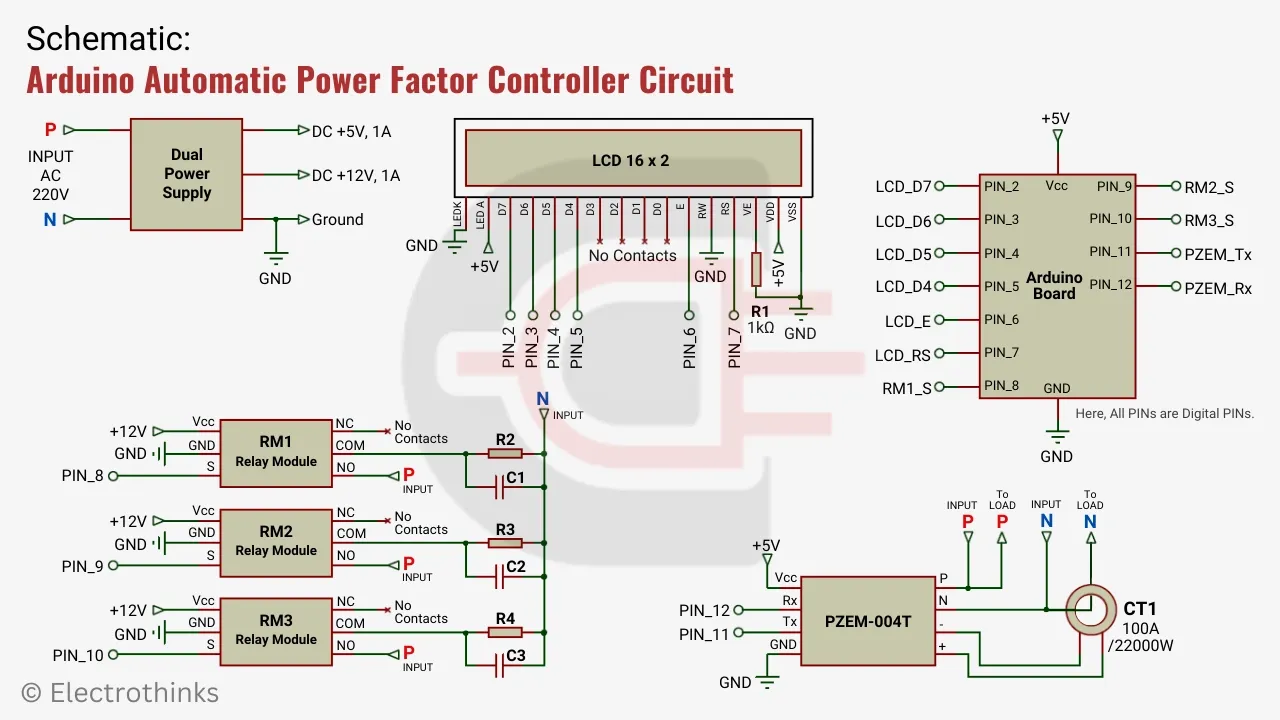
The Schematic of an automatic power factor controller circuit using Arduino is shown below.
Hardware Components
The main parts and components are,
PF Sensor. The PZEM-004T module is a sensor that measures current, voltage, power, power factor, frequency, and even acts as an energy meter. We utilized this module to measure the Power Factor (PF) without impacting system performance. It includes a CT with a rating of 100A/22,000W.
LCD. Liquid crystal is used to display the required variables for obtaining the values. A 16x2 LCD is employed to print these variables by interfacing with the Arduino board.
Relay Module. A relay is an electronic switch used to connect the capacitor to the load when the PF is low. We utilized three 12V relay modules (RM1, RM2, RM3) in the circuit, each dedicated to an individual capacitor.
Microcontroller. An open-source microcontroller board called Arduino is used here as the brain. It gathers data from the input, processes the data, and sends commands to the relay and LCD display as necessary.
Capacitor. The three capacitors (C1, C2, C3) interconnected in a star configuration with each other. These capacitors are typically used to counteract undesirable characteristics, such as power factor lag. A 2.5 Mfd capacitor is used in the model circuit to compensate for the lagging power factor. Also, damping resistors (R2, R3, R4) are connected in parallel with each capacitor to limit the peak current during the energization of the capacitor.
DC Power Supply. A fixed dual DC power supply is used to provide +5V and +12V power to the Arduino board, relay modules, and PZEM-004T module.
How to Calculate Capacitor for APFC?
As we know, the power factor is low in the case of inductive loads, whereas in resistive loads, there is no need for a capacitor since the current and voltage angle are already low. Therefore, capacitor calculation is performed specifically for the inductive load.
Follow the process below to calculate the capacitor value for the automatic power factor controller.
Suppose, your inductive load rating as - Frequency (f): 50Hz, Voltage (V): 240V, and Current (I): 0.60A.
In this case, PF Cos θ1 = 0.88
We need to improve it to PF Cos θ2 = 0.96
Power (P) = V x A = 240V x 0.60A = 144W = 0.144 KW.
Here, the phase angle for θ1 = Cos-1(0.88) in degrees.
Or, θ1 = 28.358°
Similerly, θ2 = Cos-1(0.96) in degrees.
Or, θ2 = 16.260°
Now, Reactive power (QKVAR) = P x (Tan θ1 - Tan θ2) in KVAR.
Or, QKVAR = 0.22 x (Tan 28.358° - Tan 16.260°) = 0.144 x (0.540 - 0.292) = 0.036 KVAR.
Hence, Capacitor (C) = (QKVAR x 109) / 2πfV2 = (0.036 x 10⁹) / (2 x π x 50 x 2202) = 2.370 Mfd (approx).
Generally, it is not always possible to find an exact value for this capacitor. Therefore, it is necessary to choose a standard-rated capacitor that is close to the value of 2.5 Mfd.
Source Code
Here's the Arduino sketch for the Automatic power factor controller.
Make sure you have the PZEM004Tv30 library installed in your Arduino IDE before uploading the sketch.
To install the library, go to "Sketch" > "Include Library" > "Manage Libraries" and search for "PZEM004Tv30", then click "Install" next to the "PZEM-004T v3.0 Power and Energy monitor library" by Jakub Mandula.
The following sketch will read the PF value from the sensor, display them and work to improve the power factor.
// Initialize libraries
#include <PZEM004Tv30.h>
#include <LiquidCrystal.h>

// Initialize PINs
const int rs = 7, en = 6, d4 = 5, d5 = 4, d6 = 3, d7 = 2;
LiquidCrystal lcd(rs, en, d4, d5, d6, d7);
PZEM004Tv30 pzem(11, 12);

void setup() {
  lcd.begin(16, 2); // Initialize the LCD display with 16 columns and 2 rows
  float pf = pzem.pf(); // Read the power factor value using the PZEM004Tv30 sensor
  lcd.setCursor(4, 0); // Setting cursor position to index 4, 0
  lcd.print("WELCOME!"); // Display "WELCOME!" message on the LCD
  delay(5000); // Wait for 5 seconds
  lcd.clear(); // Clear the LCD display
  lcd.print("calculating..."); // Display "calculating..." message on the LCD
  delay(3000); // Wait for 3 seconds
  lcd.clear(); // Clear the LCD display
  lcd.print("without cap"); // Display "without cap" message on the LCD
  lcd.setCursor(0, 1); // Setting cursor position to index 0, 1
  lcd.print("PF: "); // Display "PF:" message on the LCD
  lcd.println(pf); // Display the power factor value on the LCD
  delay(5000); // Wait for 5 seconds

// First condition
  if (pf < 0.95) {
    digitalWrite(8, HIGH); // Turn on relay connected to pin 8
    pf = pzem.pf(); // Update the power factor value after adding 1 capacitor
    lcd.clear();
    lcd.print("calculating...");
    delay(3000);
    lcd.clear();
    lcd.print("adding 1 cap"); // Display "adding 1 cap" message on the LCD
    lcd.setCursor(0, 1);
    lcd.print("PF: ");
    lcd.println(pf);
    delay(3000);
  }

// Second condition
  if (pf < 0.95) {
    digitalWrite(9, HIGH); // Turn on relay connected to pin 9
    pf = pzem.pf(); // Update the power factor value after adding 2 capacitors
    lcd.clear();
    lcd.print("calculating...");
    delay(3000);
    lcd.clear();
    lcd.print("adding 2 cap"); // Display "adding 2 cap" message on the LCD
    lcd.setCursor(0, 1);
    lcd.print("PF: ");
    lcd.println(pf);
    delay(3000);
  }

// Third condition
  if (pf < 0.95) {
    digitalWrite(10, HIGH); // Turn on relay connected to pin 10
    pf = pzem.pf(); // Update the power factor value after adding 3 capacitors
    lcd.clear();
    lcd.print("calculating...");
    delay(3000);
    lcd.clear();
    lcd.print("adding 3 cap"); // Display "adding 3 cap" message on the LCD
    lcd.setCursor(0, 1);
    lcd.print("PF: ");
    lcd.println(pf);
    delay(3000);
  }
}
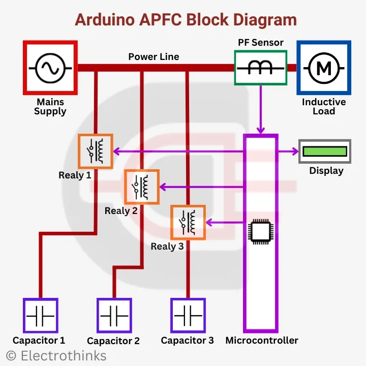
Arduino APFC Block Diagram
The block diagram of an automatic power factor controller is shown below, highlighting the key components. This diagram will greatly aid in understanding the working principle of APFC.
Working Principle of Arduino APFC Circuit
The model arrangement is done as shown in the block diagram. The working principle of the Automatic Power Factor Controller is very simple.
When a load is connected, the current starts to flow. The power factor is measured using a PF sensor with the help of the energy monitoring library (PZEM004Tv30), and the data is calculated by the Arduino. If the PF falls below the set value of 0.96, the Arduino sends a signal to the relay module, turning it on and connecting the capacitor to the load. This action helps improve the lagging power factor, bringing it closer to unity. If the PF is above 0.96, the Arduino does not send any signal to the relay module. Simultaneously, the PF value is displayed on the LCD, allowing the user to track the PF value and check for improvements.
User Guide
After assembling the project, follow the steps below to operate the model:
- Ensure that all connections are properly checked.
- Connect the 220V mains supply to the model, being careful about the phase (P) and neutral (N) connections.
- Next, connect the inductive load to the PF sensor, with the neutral connected through the CT as shown in the schematic.
- Now, turn on the power supply.
- The Arduino starts calculating the power factor and displays the status on the LCD.
- If the PF is <0.96, capacitors are automatically added one by one until the desired improvement is achieved.
- Finally, you can observe the improvement in the power factor value.
- That's all!


I tried several time but it didn't work. when i added capacitor PZEM 004t shows the decrement of PF , i did not understand why its happening
ReplyDeleteplease what is the name of the arduino board you use?
ReplyDeleteis it arduino uno?