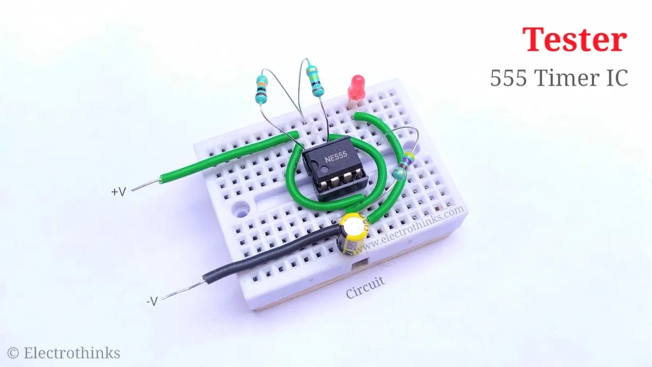
The 555 Timer IC is one of the most popular and frequently used integrated circuits among electronics hobbyists. But sometimes projects are not done smoothly with the 555 Timer, and we wonder if the IC is working properly. So, in this project, I have designed a simple circuit that can be used as a 555 Timer IC Tester.
Let's make it!
Components list
The following components are required for this project.
- U1: 8-Pin IC Base for 555 Timer (1 pcs)
- R1: 10KΩ (1 pcs)
- R2: 100KΩ (1 pcs)
- R3: 470Ω (1 pcs)
- C1: 2.2uF, 50V Electrolytic Capacitor (1 pcs)
- LED1: 3mm Red LED (1 pcs)
- B1: 9V Battery (1 pcs)
- Breadboard / PCB
- Connecting wires
Circuit diagram
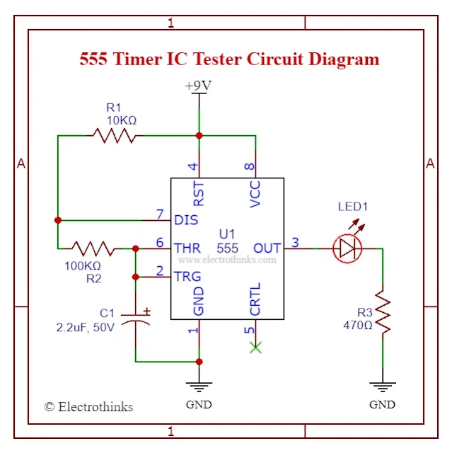
Schematic of the 555 Timer IC Tester circuit is shown below.
Circuit explanation
The working principle of the 555 Timer IC tester circuit is based on an Astable multivibrator. The circuit contains an IC 555 (U1 for testing), resistors (R1, R2, R3), a capacitor (C1), and an LED (LED1).
When DC 6 to 9V power is provided to the tester circuit, C1 will start charging through R1 and R2. Until the voltage across C1 rises above 2/3 of supply voltage, the IC's internal Flip Flop toggles. As a result, pin 7 becomes low, and C1 starts discharging.
Again, when the voltage across C1 goes below 1/3 of the supply voltage, the IC's internal Flip Flop resets, pin 7 goes high, and C1 starts charging again.
All this will happen only when your 555 Timer IC is in good condition, and an LED will start blinking as a flip-flop indicator. Resistor (R3) used for current protection of the LED.
The blinking rate of LED (LED1) can be changed by increasing or decreasing the values of resistors (R1 and R2) and a capacitor (C1).
Calculate the time duration with the help of the formula given below,
- ON Time (HIGH) = {0.693 * (R1 + R2) * C1} Sec.
- OFF Time (LOW) = (0.693 * R2 * C1) Sec.
- Total Time Period = {0.693 * (R1 +2R2)*C1} Sec.
- Frequency = [1.44 / {(R1 + 2R2) * C1}] Hz
As per our circuit, R1=10KΩ, R2=100KΩ and C1=2.2μF. If you substitute these values in the above equations, you will get the values: ON Time = 0.167 Sec, OFF Time = 0.152 Sec, Time Period = 0.320 Sec, Frequency = 3.117 Hz.
Complete circuit
I assembled the testing circuit on a breadboard and inserted a 555 IC on an 8-pin base (socket). Next, I powered it with a 9V battery and immediately LED started to blink. If the LED is not blinking, then the 555 IC is faulty.
From these observations, you can easily decide if you need to change your 555 IC.


No comments
If you have any doubts or questions, please let me know. Don't add links as it goes to spam. Share your valuable feedback. Thanks