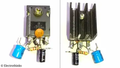
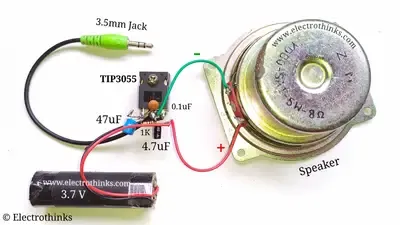
In this electronics project, we will make a simple Audio amplifier with a transistor to drive an audio speaker and produce considerable sound. It is a basic type of Class A power amplifier circuit with 3.7-12V DC input and using a minimum component. Let's make it.
Step 1: Components list
The following components are needed for this project.
| Name | Value | Qty. |
|---|---|---|
| Q1: Power Transistor | TIP35C, D718, BLD123D, C5200, MJE13007, C2625, etc. | 1 |
| LS1: Speaker | 5-10W | 1 |
| R1: Resistor | 1KΩ | 1 |
| C1: Non-polar Capacitor | 0.1uF | 1 |
| C2: Polar Capacitor | 47uF 25V | 1 |
| C3: Polar Capacitor | 4.7uF 50V | 1 |
| Stereo 3 Pole Male Jack | 3.5mm | 1 |
| DC Power Supply | 3.7-12V | 1 |
| Wire | As per required | |
| Soldering Kits | - | 1 |
| PCB (Optional) | - | 1 |
Step 2: Single transistor Audio amplifier Circuit diagram
The schematic of a simple single transistor audio amplifier circuit shown below.
Circuit explanation
The Audio amplifier circuit is constructed using a single Transistor and Resistor, Capacitors. The Transistor acts as an amplifier by amplifying the audio input signal. This is a Class A power amplifier.
When a DC bias voltage is applied across the Emitter-Base (VEB) junction of transistor, it remains in a forward-biased condition that can be maintained irrespective of the low audio signal’s polarity. So, the transistor always biased in ON state. Thus, during a complete cycle of the audio input signal, the transistor produces minimum distortion in the maximum amplitude of the audio output signal, and we hear loud audio/music from the Audio speaker.
The transistor must have a high collector current (IC). I used a TIP3055 N-type transistor for this amplifier, it is a 70V power transistor along with a 15A of collector current.
You can use any of these: TIP35C, D718, BLD123D, C5200, MJE13007, C2625, etc.
Pin configuration of SOME transistors may be different from TIP3055, check pin configuration before you use it in the circuit. It is mandatory to connect a large aluminum heatsink with Transistor to accommodate heat dissipation!!!
The resistor R1 is used as a base resistor which is providing sufficient base current to drive the transistor in saturation point.
C1 capacitor is used for noise canceling and improving the audio amplifying.
A capacitor C2 is used for isolating the transistor base with the input supply source so that the base voltage or current could not affect the audio input source. Also, it blocks DC and only passes AC from the audio input.
C3 capacitor is used to improve the audio Bass and audio quality of the Speaker.
This amplifier can drive a 5W to 10W 🔈 loudspeaker (I used a 5W 8Ω Speaker).
The operating input voltage of this audio amplifier is 3.7V to 12V DC, and a 3.5mm Stereo 3 Pole Male Jack (Pins connection according to the diagram) used to plug into the female jack of the audio source device.
Step 3: After soldering
Step 4: Demo & Testing - Single transistor Audio amplifier
| Testing the Audio Amplifier. |
The overall efficiency of the amplifier circuit has some major drawbacks. As you know, the circuit is a basic construction of class A amplifier, almost a large amount of current is lost as heat dissipation across the Transistor. Also the sound quality is considerable.


Can we add one another transistor , if yes then how? Can it improve its performance?
ReplyDelete