In this electronics project, we will make an Emergency 9 watt LED inverter using a Mobile phone charger transformer and NPN transistor. This inverter (driver) provides power for LEDs (like - white, blue, UV, but also any other) from 3.7V single cell (battery). Let's make it.
9W LED inverter Components
The following components are needed for this project.
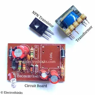
- Mobile Phone charger.
- 1W LED (9 pcs).
- 20-100Ω Resistor (1 pcs)
- 3.7V Lithium Battery (1 pcs).
- Wire (As per required).
- LED Bulb Body (1 pcs) - Optional.
9W LED inverter Circuit diagram
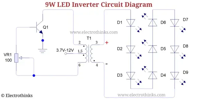
Schematic of 9 Watt LED inverter circuit shown below.
Circuit Explanation
The 9W LED inverter circuit is an oscillator circuit, which has a striking resemblance to the Joule Thief circuit.
See also: Joule Thief Circuit Working Explanation.
Using a Digital Multimeter, you can find the Mobile phone charger transformer windings resistance. In my case, the primary winding L1 (output of this circuit) resistance is 9Ω, and the other windings (secondary L2 and feedback L3) resistance is 1Ω.
You haven't any old Mobile phone charger? - Don't worry! You can also make this inverter using a Toroidal or EE-type transformer and an NPN transistor (Package: TO220).
The windings of the Transformer as follow -
- Primary (L1): 250 turns using 0.01mm insulated copper wire.
- Secondary (L2): 12 turns using 0.25mm insulated copper wire.
- Feedback (L3): 6-8 turns using 0.25mm insulated copper wire
I used an MJE13003 transistor from the Mobile phone charger circuit board. You can also use MJE13005, BLD123, TIP41C, TIP3055, or any power NPN transistor. This transistor gets very hot, so you must be used a heatsink.
The resistor R1 value is between 20-100Ω (I recommended to you use a 100Ω Potentiometer for better result).
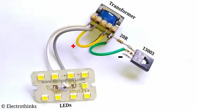
This inverter circuit can drive 9W LED. I used a series of 9 SMD LEDs (each LED is 1 watt).
The circuit input voltage should be 3.7-12V DC. The output voltage is 220-700V AC without load. But, you can not drive a CFL lamp or any 220V load because of voltage fluctuating. Only you can drive LEDs as an emergency lamp.
9W LED inverter circuit after Soldering
Demo and Testing - 9W LED inverter
Testing the 9W LED Inverter.


Nice & Easy tool to make for home ... thanks for sharing
ReplyDeleteWelcome...
Deletesubhajit pls call me 9714108555 for project plan
ReplyDelete