A Neon Line Tester is one of the important tools of an electrician. We can use it as a screwdriver or check the presence of electricity in a circuit. But the question arises do you know how does a neon line tester work, what inside of it, why Neon line tester does not work on DC supply? Let's learn about Neon line tester, construction, and circuit diagram with the working explanation.
Below we shall focus our attention on the various aspects of Neon line tester.
What is Neon Line Tester?
Line tester or Neon line tester is a primary tool used to detect the live / line / hot / phase wire or conductor of an electrical circuit. It is one of the important tools of an electrician. The voltage range of the Neon line tester is between 110-700 volts in AC supply.
Never try to work on electricity without proper guidance and care.
- Ensure that the Line tester is working properly.
- Ensure that the Line tester is not broken.
- Don’t touch the open electric wire even Neon Line tester shows the absence of phase or hot supply.
- Never try to test the presence of phase or hot wire of any high voltage supply source with Neon line tester.
Now, we learn the construction details of the Neon line tester below.
Construction of Neon Line Tester
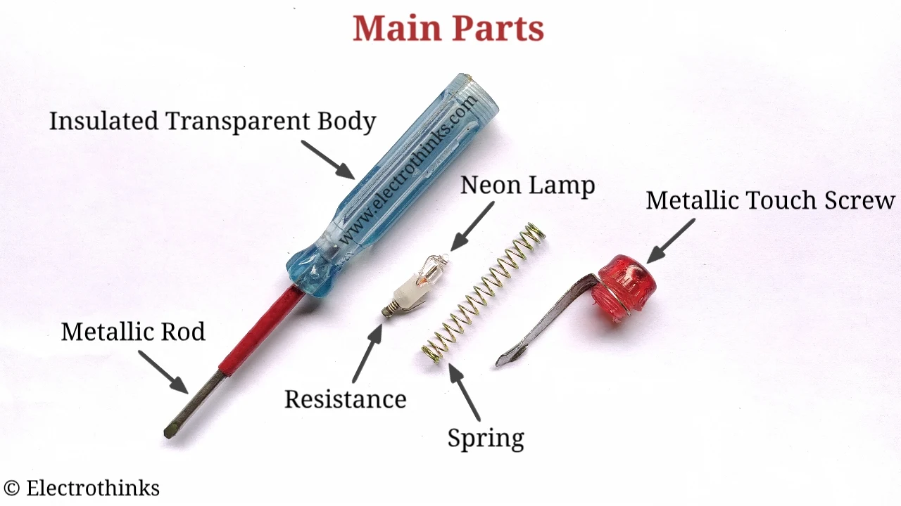
The Neon Line Tester is a tool used to identify the Phase or Live Wire. This tester is a combination of six different main parts namely metallic rod, resistance, neon lamp, spring, metallic touch screw, and insulated transparent plastic body.
Metallic Rod
In Neon line tester, one end of a cylindrical metal rod is designed as a flat screwdriver, but the main part of the rod resides inside the insulated transparent body. This helps the line current to flow towards the resistance.
Resistance
One end of resistance gets connected with the metallic rod, and another gets connected with the neon lamp. The resistance of neon line tester reduces the flow of current through it, this makes the tester a safe tool. This resistance value is higher than 1.5MΩ.
Neon Lamp
A neon lamp is consists of a small glass capsule that contains a mixture of neon and other gases at low pressure and two electrodes (an anode and a cathode). Here, one terminal of neon lamp gets connected with resistance, and another terminal gets connected with metallic spring.
Spring
It is used to make a connection between Neon lamp and metallic touch screw.
Metallic Touch Screw
Metallic touch screw is used to tight all the above components inside the Insulated transparent plastic body.
Insulated Transparent Body
This insulated transparent body made with hard plastic helps to protect the users from electric shock.
Before we learn the working principle of Neon line tester we must learn about Electric wires. Mainly all electrical devices and appliances use a maximum of three wires and a minimum of two wires for the electrical supply.
These wires are separate from each other and are characterized by specific names.
- Phase Wire (Live Wire or Hot Wire).
- Neutral Wire (Cold Wire).
- Earth Wire (Used for safety purposes).
Phase Wire in alternating current supply is very dangerous and it has a higher potential difference from Neutral or Earth wire.
As we know, the circuit current flows when two different potential wires are in contact. This potential difference between the two wires in the terminal is called "voltage".
For example,
In India, the potential difference between Phase and Neutral is specified as 220 volts, while the difference between neutral and earth is about 5 volts.
Working principle of Neon Line Tester circuit
Here is the working principle of neon line tester. When the metallic rod end of neon line tester comes in contact with the Live (Hot) wire, users touch the rear metallic touch screw a circuit gets completed (current moves through the metallic rod).
As we know, the metallic rod is connected with resistance. The electric current passes through the resistance. A large amount of electric current drops due to resistance and a small amount of electric current passes through it to the neon lamp and reaches till the metallic touch screw which is in contact with the user's finger.
This small current passes through the user's body (It undergoes body resistance RBody and body capacitance CBody and creates a Stray capacitance) to the earth and completes the circuit. Instantly a current starts flowing, and the gases of Neon lamp start glowing. This indicates that the Phase of electric supply is present in the touched wire.
Frequently Asked Question (FAQs)
After reading this you may have some questions that are discussed below.
Why Neon line tester does not glow on DC supply?
The main reason is in DC supply negative/positive terminal is not connected with the ground. When an electrician touches the DC source terminal means, the neon lamp of Line tester does not glow due to there is no path to flow of current.
Who Discovered Neon lamp?
Nikola Tesla (Serbian-American inventor).
Why does the Neon line tester Glow in Line not in Neutral?
In AC (Alternating Current) power only one of the wires (line/live/phase/hot) changes it's potential, while the potential of the other one neutral remains constant (neutral voltage zero). So, when you put the tester on the neutral wire, the neon lamp in the tester doesn't find enough voltage to glow up. But, it finds a voltage difference in line wire and current flows and the tester glows.
Why don't we get Shocked by Line tester?
Inside the tester, a resistance (R) limits the current flowing through your body to safe minimum levels. So we do not get electric shocked by line tester.


No comments
If you have any doubts or questions, please let me know. Don't add links as it goes to spam. Share your valuable feedback. Thanks