A compact fluorescent lamp or CFL Bulb, also known to us compact fluorescent light, energy-saving light, and compact fluorescent tube. Fluorescent lamps and CFLs are very similar, just a compact version of a fluorescent lamp with a compact electronic ballast in the base of the lamp that is smaller and easier to install.
One of the biggest advantages of a CFL Bulb is its low energy consumption, which also produces less heat, has a much higher lifetime compared to incandescent or halogen lamps, and produces pleasant light.
Incandescent lamps replacing with CFLs result in cost-efficient in terms of electricity bills that together with its long life offset the higher purchase price of the lamp. But, do you know how does it work, construction of CFL Bulb, ballast circuit diagram? Let's learn about the CFL bulb and Ballast circuit diagram with working explanation.
CFL Bulb Construction
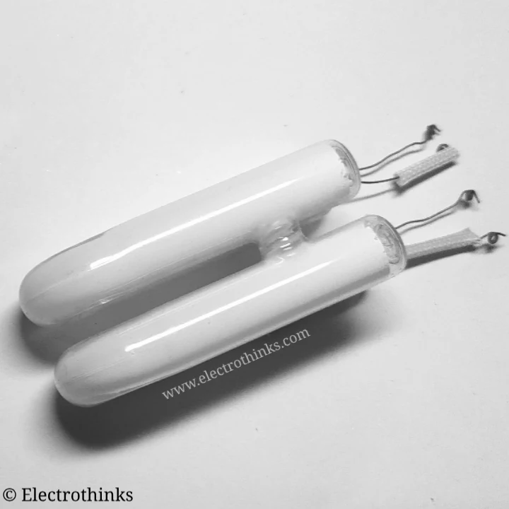
The basic construction of a compact fluorescent lamp (CFL) consists of a fluorescent glass tube that is curved or spiraled, and a compact electronic ballast in the base of the lamp.
A CFL uses a vacuum glass tube which is very similar to the strip lamps (commonly known as Tube light). The tube has two electrodes on both ends which are treated with Barium.
How does a CFL Bulb Glow?
The CFL Bulbs consist of a switched-mode converter (Electronic Ballast) that functions on a very high frequency and acts as a replacement of the Electrical Choke, and Starter assembly.
When this high-frequency electricity is passed through a filament (usually made of tungsten) of electrodes, temperature becomes about 900º C. A beam of electrons generates which is further accelerated by the potential difference between electrodes.
These accelerated electrons strike Mercury and Argon atoms which arise of low-temperature plasma. In this process generates the radiation of Mercury in Ultra Violate (UV) form.
Then the UV light hits the phosphor coating on the inside of the fluorescent tube, it is to convert UV light into visible light, the whole process is done in a sealed vacuum tube.
To complete this entire process typically takes 30 seconds to 3 minutes. Once the lamp starts operating, a much lower voltage can be maintained the current and light output.
As compared to incandescent lamps, the little heat produced in a fluorescent lamp is just a byproduct, and most of the energy is converted into visible light.
CFL bulb Ballast Circuit diagram
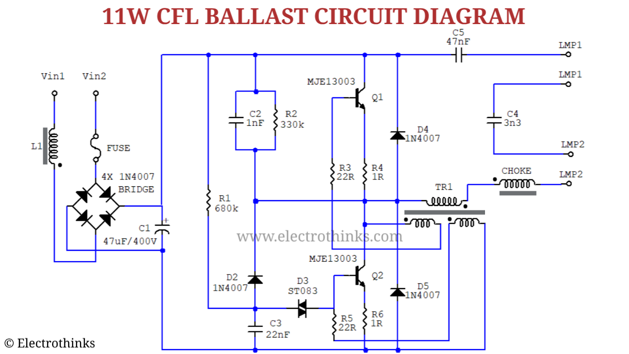
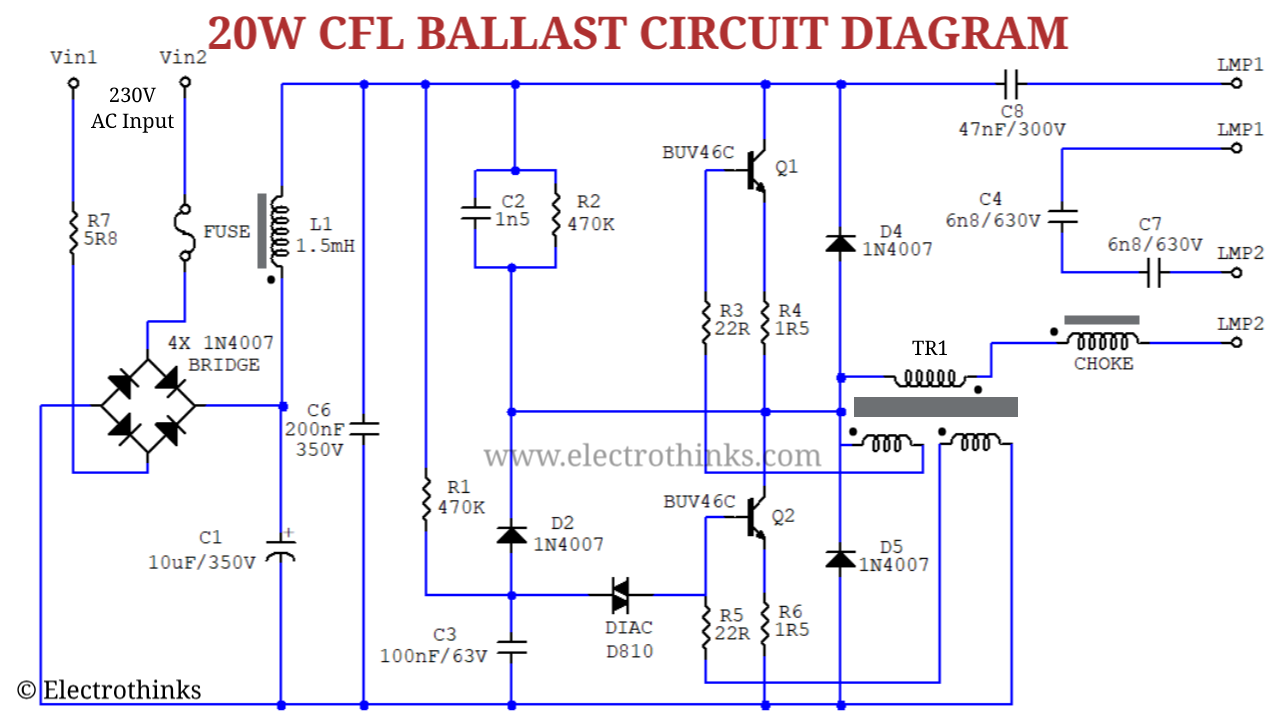
The CFL bulbs present in the market have different wattage such as 5W, 9W, 11W, 15W, 20W, 25W, 30W, etc. So the internal ballast circuit is also different. Below is shown the circuit diagram of some CFL ballast boards.
Working principle of CFL bulb ballast circuit
Many manufacturing companies make CFL bulbs, and their circuit diagrams of electronic ballast also different. But all of them maintain the actual block diagram of the CFL bulb ballast.
The working principle of CFL bulb ballast circuit is explained in detail here. If you completely understand the block diagram, then you can easily understand the CFL bulb ballast circuit of any company. Generally, all the CFL bulb ballasts follows that
The circuit board of a CFL bulb ballast circuit is a combination of four different circuits.
- EMI Filter Circuit.
- Full-Wave Rectifier Circuit.
- DC Filter Circuit.
- Inverter circuit.
In the CFL bulb ballast circuit, a series resistor is connected between the phase input terminal and EMI filter circuit. It is connected to limit the overload and short circuit current. In some CFL bulb ballast, a fuse is used instead of a series resistor. This resistor has a very low value up to 22 Ohm.
After a series resistor (or fuse), an Electromagnetic Interference (EMI) filter circuit is connected. The EMI filter consists of one inductor in series, and one capacitor in parallel which blocks or reduces electromagnetic interference from the input.
Then a Full-wave bridge rectifier circuit is used to convert AC to DC. The Bridge Rectifier Circuit consists of four PN Junction Diode.
A polarized capacitor is connected in parallel for filtering purposes of impure DC coming from the rectifier circuit.
Next, An inverter circuit using two transistors are used. The transistors create a high-frequency square wave AC signal and give it to the Choke. The frequency created in CFL bulb ballast 20 KHz to 80 KHz.
The choke increases the voltage level up to 1000V. At the starting time, the voltage across the CFL tube is 1000V. Once the CFL bulb glows the voltage across it decreases to 230V and the ballast circuit allows to flow a low current to the tube.


good explanation
ReplyDeleteThanks!
DeleteIt would be better if you can demark with circle the emi,filter,inverter etc circuit in the actual circuit diagram
ReplyDeleteThanks for your advice :)
DeleteJust wondering, if we not connect the bulb,the voltage will constans at +-1kV. Maybe we can built a fly swatter or something like it from the cfl circuit ?
ReplyDeleteThis is not possible! Because the output is only 1kV constant for the starting time. After some time, it decreases to 230V.
DeleteGood Explanation and it is very helpful
ReplyDeleteI am missing some essential parts from the description:
ReplyDelete- the way the inverter is working (you could describe the series multivibrator circuit used in these lamps) and why is this solution favored to parallel circuits.
- how does the starting voltage (i.e. 1000V) decrease to line voltage (i.e. 230V)
Very clear and simple explanation
ReplyDelete