Mosquitoes are like tiny vampires and are present in every corner of the world. They are truly a nuisance, as they not only cause painful itching in the bite area but also have the potential to spread horrible diseases such as malaria. No matter how much you try to reduce their population, mosquitoes just keep growing in numbers. A cool way to eliminate these "devilish" insects is through electrocution.
A mosquito killer bat is designed just for this purpose. It is also called an electric flyswatter, mosquito bat, racket zapper, or zap racket. These devices are handheld and resemble a badminton racket or tennis racket in appearance. The device is activated by pressing and holding the button. The grid of the device is electrically charged; when a fly nearly bridges the gap between electrodes, a spark jumps through the fly and high voltage burns it. Inside the handle of a mosquito killer bat contains an electric rechargeable battery and a circuit board.
Mosquito Killer Bat Circuit Diagram
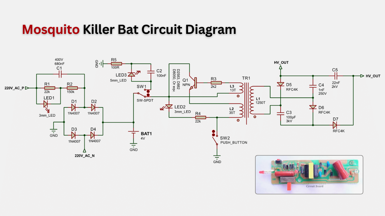
The schematic of a mosquito killer bat circuit is shown below. This circuit is similar to the circuit in an electroshock weapon or stun gun. However, the output voltage of the mosquito bat is much lower, typically about 500 to 3000 volts of direct current.

Working Principal of Mosquito Killer Bat Circuit
The mosquito killer bat, also known as a mosquito flyswatter, works through the combination of three main circuits: the battery charging circuit, the inverter circuit, and the voltage multiplier circuit.
Battery Charging Circuit

A mosquito killer bat circuit board receives power from a rechargeable 4V electric battery. Therefore, a charging circuit is needed to charge the battery. Typically, a Transformer-less or capacitive power supply is used. After a full charge, the battery provides service for 5 to 8 hours (depending on the user).
Inverter Circuit

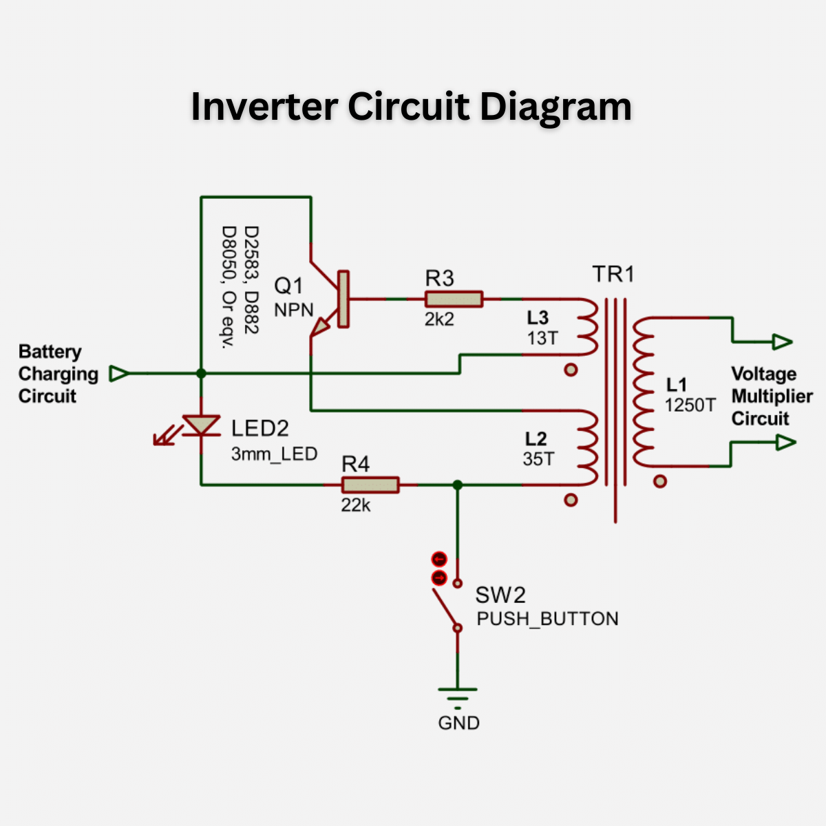
The inverter circuit is the most crucial component of the mosquito killer bat circuit. This circuit converts the low DC voltage to high-voltage AC voltage, about 200 to 230 volts. The blocking oscillation concept is utilized in this inverter circuit, where only a single NPN transistor, a resistor, and a step-up transformer are employed.
Here is a small EE-type ferrite core transformer typically used with no air gaps between them. The primary winding (L1) has 35 turns of 0.2mm copper wire, the feedback winding (L2) has 13 turns of 0.2mm copper wire, and the secondary winding (L3) has 1250 turns of 0.05mm copper wire.
Voltage Multiplier Circuit

Due to the low inverted voltage, which could not build up the required voltage to create the spark between the two electrode grids in the mosquito killer bat, a voltage multiplier circuit is needed to Step up the voltage to the required level. The maximum continuous flow of most electric flyswatters is less than 5 milliamps (mA) of current after the initial discharge. This current level is safe, even when flowing from one arm to another, but not for mosquitoes.
Flashlight Circuit

Nowadays, some mosquito zapper bats come with single or multiple LED flashlights to be used as emergency lights. The light can be turned on using the ON/OFF switch on the bat handle, which allows the switch to select three modes: turning the flashlight on, turning it off, and activating the mosquito killer bat circuit.


What is size of EE core
ReplyDeleteCore Type: EE16.
DeleteDimension: 17mm x 16mm.
Which transistor is used in this Chinese mosquito zapper circuit?
ReplyDeleteYou can use d2583, d882, d8050 or equivalent transistor.
DeleteGreat explanation sir...
ReplyDeleteThanks
DeleteHow many types of batteries are used in MK Bats. Just myself checked and found atleast two types. One is 4V/0.4Ah but in another bat (model EN-07MS) the battery is little bit larger and may be of higher volts or Ah. Nothing is mentioned on this battery. So just I wanted to clear if some more types are used. Subhan it, can we share our contact nos.for any furthermore.
Deletewhat is the total cost circuit with battery.
ReplyDeleteYou will not find these Circuit board readymade in the market or online stores.
DeleteYou have to buy a Mosquito Killer Bat first.
After that, when you open it, you will get a circuit board and a rechargeable battery (make sure the bat has a rechargeable facility).
Exactly correct suggestion
DeleteC1 specification 0.68 micro farad and voltage?
ReplyDeleteThe voltage of this capacitor is 400V.
DeleteWhat will be rating of the battery
ReplyDeleteMostly, a 4 V 1000-1500mAh lead acid battery is used.
DeleteHowever, there is some bat that uses one or more 3.7 V 2000mAh lithium batteries and for this, the charging circuit is also different (you can use here tp4056 module).
Is 223 outout capacitor is 2kv AC or 2kV Dc
ReplyDeleteIt is 22nF 2KV AC and pulse metallized polypropylene (PP) film capacitor.
DeleteIs the transformer turns ratio are correct to step up 3V to 200V?
ReplyDeleteYes! you can follow the same.
DeleteHi I need output 10w only for project work what changes I need to do in this circuit
DeleteReplace the transistor with power transistor like TIP35, TIP3055, etc.
DeleteWhat may be the fat for fluctuating dc charging voktsge 6volts. It is fluctuating between 6 to 80 volts. Changed .68capacitor also. Please give hints.
ReplyDeleteall didode are 1N4007?
ReplyDeleteYes!
DeleteHowever, you can replace the diodes d1, d2, d3 with Fast recovery diode.
hello is there any way that i van change the frequency of this circuit to 1 ghz ?
ReplyDeleteIt could be!
DeleteReplace the transistor with a power MOSFET. However, I am not sure about the output frequency.
Can you explain on how does the oscillation is generated?
ReplyDeleteWhen the power supply to the transistor is switched on initially, electronic noise in the circuit provides a non-zero signal to get oscillations started.
DeleteThe noise travels around the loop across the two winding (L1, L2) of the transformer and amplified on a square wave at a single frequency and step-up the input voltage through secondary winding (L3).
What will be the current through base of transistor.....
ReplyDeletethis transformer primary inductance value and winding connection start & end how is the find?
ReplyDeleteplz find ?
Can I use it without battery always connected with ac power removing switches and arranging blue LED in it to attract mosquitoes instead of chemical mosquito repellent..
ReplyDeleteNo. This is not a good idea, because the output of the charging circuit does not give pure D.C. output so the transistor may be damaged.
DeleteI advise you to use a D.C. 5V 0.5-1A adapter for the direct powering of the mosquito killer bat circuit. Therefore, you need to disconnect the charging circuit and battery from the circuit.
If I have to use a 12V dc adaptor, without battery and charging circuit what changes are required in the circuit for continuous stand alone operation
ReplyDeleteCan we say that it is a type of static convertor?
ReplyDeletewhat is the specification of stepdown transformer
ReplyDeleteAll the details are given... read the post carefully and get the answer.
DeleteWhy transformer leakage/Fail again n again in PCB
ReplyDeleteCheck the transformer winding (direction, connections, or turns).
DeleteI have developed mosquito circuit after 15-20 times spark then Transformers are damage pls suggest why fail ..pls tell me solution how to resolve this problem..
ReplyDeleteIs the output voltage dc
ReplyDeleteNo, the output is AC ~2000V (approx).
Deletepls what is the rating of the transformer use
ReplyDeleteAvailable in the article.
DeleteCharging voltage for the battery is showing more than 200v in mosquito bat..pl explain
ReplyDeleteIt's a capacitive power supply system. Without load, the X-rated capacitor wants to reach its highest capacitor voltage with low current (e.g. if you use a 400v voltage dropping capacitor, then it wants to reach 400V in no-load condition). But, when you connect an acid battery or LED light as a load to the output, the voltage comes down according to the load.
DeleteHi Sir, meant if i measure 230V (Which i presume is line voltage in Malaysia) with a Battery attached, can i said that the battery is faulty ?
DeleteAnd there is another unit when i attached the battery, charging voltage is 0
GOOD, NICELY EXPLAINED
ReplyDeleteThere is no protections in the circuit (fuse, varistor....)
ReplyDeleteMr Berman kya aap se phone per baat ho sakti hai mujhe new circuit design karbana hai my place delhi
ReplyDeleteExhaustive explanation .Very systematic .Keep it up Shubhojit.
ReplyDeleteI suppose the ckt is designed for 4 v lead acid battery .Does it have a overcharge protection incorporated?
ReplyDeleteWhy transistor overheat? Transformer seems ok but no output. When also removed traforrmer, no heating of transistor s882.
ReplyDeleteWhat is the equivalent for KE HE D9 CU Transistor.? Can I use D 882 in place of the above mentioned NPN transistor? Please advise. Thanks.
ReplyDelete